 da
da de
de es
es fr
fr it
it nb
nb nl
nl pt
pt sv
sv fi
fiSiemens Simtec 71

Many mechanics would agree: the 125 hp Z18XE is a well-known and widely used Opel engine block. The Corsa C, Tigra Twintop, Astra G, Vectra C, Omega B, Meriva and Zafira were all available with this 1.8. However, in this article, we do not want to spend too much time on the engine block itself.
We are way more interested in the Engine Control Unit which ensures that the engine block functions properly: the Siemens Simtec 71.
What becomes defective in most cases?
Let’s not beat around the bush: it is interesting to talk about the things that can go wrong. That being said, the Simtec 71 does not disappoint us since it has several weaknesses. We often come across ignition coils of which one or more are not being controlled. Besides, we also see this at the injectors and the adjustment motor for idling. Though, it is useful to mention that the Z18XE uses an electric throttle body. So, in case error codes appear that have to do with idling control or the throttle body, first check the throttle body itself. Do not suspect the ECU before knowing that the throttle body functions properly.
A lack of control by the ECU can have many causes, but almost each one can be traced back to heat and vibrations. Fortunately, the Simtec 71 is not assembled directly onto the engine block, like for instance the Delphi Delco Multec, but still, the circumstances under the hood are not ideal for the delicate electronics that are used in ECUs. That is why now and then, a component in the ECU or a wire connection on the circuit board becomes defective. It is also exactly the reason why we come across other malfunctions, such as errors on the 5 Volt circuit: really every component can become defective due to heat and vibrations.
Where there are electronic defects, error codes can be found and the Simtec 71 is not an exception. In case of lack of control on various components, the ECU will immediately show:
- P0201 Injector 1 Circuit Malfunction / no signal
- P0202 Injector 2 Circuit Malfunction / no signal
- P0203 Injector 3 Circuit Malfunction / no signal
- P0204 Injector 4 Circuit Malfunction / no signal
- P0325 Knock Sensor Circuit Malfunction / no signal
- P0351 Ignition Coil 1 Circuit Malfunction / no signal
- P0352 Ignition Coil 2 Circuit Malfunction / no signal
- P0353 Ignition Coil 3 Circuit Malfunction / no signal
- P0354 Ignition Coil 4 Circuit Malfunction / no signal
Though, the error codes regarding the electronically controlled throttle body are more difficult to recognise and might give you the idea that the problem is located in the throttle body itself. However, the throttle body is by no means always the cause of the complaints. Good control by the ECU is crucial.
P0120 Throttle Body Potentiometer 1 Voltage too high in combination with P1550 Electric Throttle Body in Emergency Mode / limited capacity
P0220 Throttle Body Potentiometer 2 Voltage too high
Fortunately, all of the above defects are well solvable. We developed a special remanufacturing trajectory for the Simtec 71 in which we go through all weaknesses and their sources.
Remanufacturing: the process
The ECU goes through a process that is way more comprehensive than simply repairing. We know that certain parts of these ECUs are sensitive and we want to be absolutely certain that our remanufactured ECUs last at least as long as new ones. It is for that reason that we guide ECUs through a standard process instead of solely solving the encountered defects.
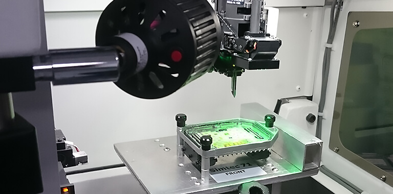
This trajectory starts with a comprehensive entry test. Our Vision test environment is perfect for this task, since it enables a complete car simulation. After this, the silicone gel is removed by immersing the ECUs in a bath with special solvent. Now that all components are unprotected, we can start with checking all Bare Die connections and removing the hybrid connections. This is a delicate process, but not a problem for us, looking at our years of experience.
After cleaning and removing, all connections (wire bond connections) are reassembled by highly advanced equipment that attaches new wire connections to the existing contacts by applying ultrasonic vibrations. This is what we call ultrasonic wire bonding. The equipment was programmed by ourselves and configured in such a way that every new bond connection is automatically tested by means of a “pull test”. This enables us to be sure that every bond connection is sufficiently robust to withstand vibrations and temperature fluctuations. The new connections are even stronger than the original ones.
Various components on the circuit board are also replaced. In some cases, installing a new circuit board including its components is needed. We developed these circuit boards ourselves and they make the ECU more reliable than a new one. In most cases, we are lucky to have the possibility of reading and saving ECU data. After replacing the components, the data is replaced so in most times the customer does not have to reprogram.
After this, it is time for the end test. This test is performed to see if all functions work like they should. Our Vision test environment enables us to perform a burn-in test, with an actual increase in temperature in the ECU. In case of a successful test, the remanufactured ECU will be protected by a layer of special gel. We use our own developed cover to close the ECU.
If the ECU, after this process (or already when it enters our building) seems to have complaints, we look at it more specifically. There are many opportunities when it comes to diagnosing and solving problems. To get more insight into the things that could become defective, we will broadly explain what we encounter in the ECU.
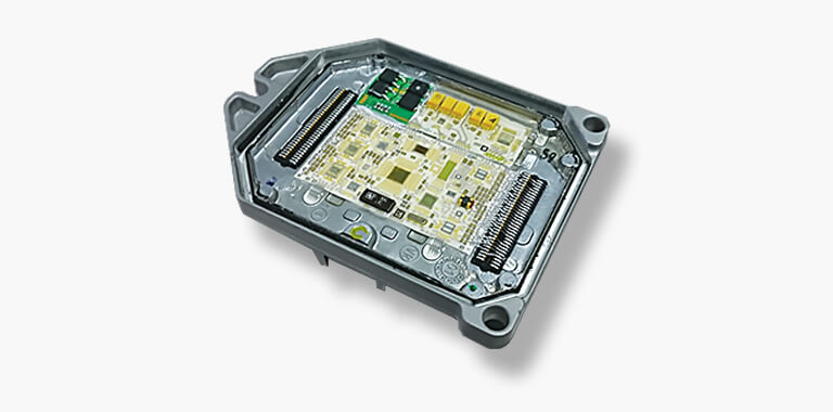
The Siemens Simtec 71 in detail
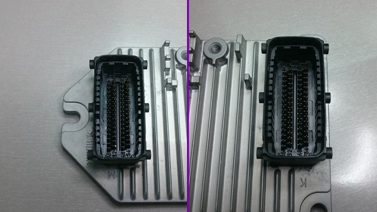
Similar to, for example, the Delphi Delco Multec ECU, the Siemens Simtec 71 is easily recognised by its looks. Two large 64-pin plugs at both sides of the circuit board connect the ECU with the wiring harness. Circuit diagrams allow us to find out what each pin receives or controls, which provides an easier diagnosis up until the plug. At first glance, the ECU does not seem that complex.
However, the inside of the ECU is much more complicated. The ECU uses two separate ceramic circuit boards that are both connected by a large number of hybrid connections. The components on both PCBs (Printed Circuit Boards) are all meant to support the central processor in its operations. Think about CAN filters and ignition drivers. Just an EEPROM or flash memory is certainly not enough for the processor. To give everybody some more insight into the functioning of the ECU, we’ll discuss the most important components that we encounter.
Analog – digital converters
Sensors like mass air flow sensors and lambda sensors are produced in such a way that they release a variable voltage which depends on the measured value. There’s not much the ECU can do with this value, since the processor is only able to process digital numbers. It is for that reason that converters were placed into the ECU that convert these voltages into 10-bit values, which enables the processor to process them.
Digital – analog converters
Sometimes, it is necessary to convert a digital voltage back to an analog voltage after it went through the processor. Certain actuators are able to adjust the valves to a more open or closed position, depending on the received voltage. The digital – analog converters ensure that also these actuators function properly.
Signal conditioners
Analog values enter in all sorts of forms, but the convertors always convert these values in the same way into a digital number. Since this is not always the best option, signal conditioners were placed on the circuit board. These conditioners change the analog values into a value that is useful for the converting process.
The value of a lambda sensor varies for instance between 0V and 1,1V, but if the convertor works between a value of 0V and 5V, the conversion will be less precise. To tackle this problem, the conditioner enlarges the value, for example 4 times. For a 5-Volt convertor, a value between 0V and 4,4V allows a more accurate conversion to a digital number.
High-level digital output
Nowadays, ECUs control so many things, not just ignition and injection, but in case of the Multec also the cooling fan. These components require a powerful input (relatively high number of amperes at 12V) that cannot be generated by the delicate electronics in the ECU. To solve this problem, the minimal output that the processor releases is used to control a transistor (driver). This transistor ensures a powerful output that is needed to provide components with the right amount of power. However, this output does not always immediately reach the component. The cooling fan for example requires such large output, that the (by the transistor) strengthened output is still not strong enough. In such case, the output of the transistor is used to control a relay.
This entire chain of components is easiest described as a three-stage rocket. It seems like a cumbersome system, but it works very well in practice.
Communication chips
Today, cars are full of all sorts of computers. The ECU is not the absolute ruler anymore. The consequence of all these computers is that often multiple ones simultaneously require the same signal. Besides, computers also need to communicate with each other. If the ECU notices a defect, it would be convenient if the engine failure light in the dashboard switches on. To make all this possible, the CAN network was invented. All CAN messages that are received and sent by the ECU are all processed by a central communication chip. Actually, you can see this chip as the logistics centre of the ECU. Per second, literally hundreds of messages are being sent and received. That is also the reason that the CAN network is able to work with speeds up to 500 Kbps.
The Simtec 71 ECU is a lot more complex than you would expect from first sight. This makes making a correct diagnosis of a defect in the ECU very difficult. Fortunately, ACtronics is a specialist in this field. The Simtec 71 does not hide any secrets from us anymore. In case you experience problems with this ECU, please contact us and we will look for an adequate solution.
Disassembling the ECU
The ECU is not always positioned at the same place but often easy to reach. We advise to always first disconnect the battery and to keep radio codes at hand if possible. The rest of the disassembly is rather simple: disconnect both plugs and loosen the screws at the corners. After that, the ECU can be taken out of the car. Do not forget to include the key and the transponder in your package, because of the immobilizer of the ECU.
Video
Time goes fast and our processes and equipment change just as fast. Therefore, it might be interesting to see how the remanufacturing process of the Siemens Simtec 71 once started. Take our newest equipment in mind and you will have an idea of today’s process.