 da
da de
de es
es fr
fr it
it nb
nb nl
nl pt
pt sv
sv fi
fiTCU Mercedes-Benz Siemens FTC (722.7)

Mercedes-Benz ran into quite a bit of trouble when it decided to add a small vehicle to its range. The car not only had to be compact and practical but also had to deliver a lot in terms of comfort and luxury. After all, it was a Mercedes-Benz. The 722.7 gearbox has the layout of a conventional manual gearbox, but uses a torque converter and several small hydraulic clutches to shift between gears.
Known complaints and error codes
Known complaints
- An “F” appears on the display
- The car goes into limp mode
- The gearbox no longer shifts
- The gearbox shifts randomly to “N” or an illogical gear
- The car won’t start
Can be remanufactured
| OBD II | Description |
|---|---|
| P1840 (2120) | PWM solenoid valve 1 / 4 shift |
| P1841 (2121) | PWM solenoid valve 3 shift |
| P1842 (2122) | PWM solenoid valve 2 / 5 / R shift |
| P1843 | PWM solenoid valve torque convertor lockup clutch |
| P1844 | PWM shift valve circuit |
| P1850 (2204) | Transmission RPM sensor Y3/7n1 |
| P1858 (2227) | Starter lockout contact |
| P1884 (2123) | PWM shift valve pressure |
| P1897 | Control module N15/7 faulty |
| P1903 | Control module N15/7 faulty |
Remanufacture may be possible (additional diagnosis required)
| OBD II | Description |
|---|---|
| P1895 (200a) | Internal fault in control unit |
This error code will never actually appear independently. Therefore, look carefully at the rest of the error codes to make the correct diagnosis.
| OBD II | Description |
|---|---|
| P1709 | Park / Neutral switch |
| P1756 | Selector lever implausible |
| P1872 | CAN signal from gear regognition module faulty |
| P1875 | CAN communication ESP |
| P2031 | No signal or error signal from control unit N15/5 |
| P2210 | Selector lever coding is invalid |
| P2211 | The selector lever is in an intermediate position |
| P2212 | The selector lever position is implausible |
| P2318 | Fault in CAN communication with control unit N15/5 |
| P2333 | The CAN signal from control unit N15/5 |
| P2338 | The CAN signal from control unit N15/5 |
| 2310 | CAN communication with TCS failed |
| 2311 | CAN communication with ECU failed |
| 2312 | CAN communication with ECU failed |
| 2315 | CAN communication with instruments failed |
| 2316 | CAN communication with A/C failed |
| P240C | The CAN signal for the selector lever position from control unit N15/5 |
These error codes may indicate that the gear selector lever is defective. In many cases, this is also revisable.
 Cannot be remanufactured
| OBD II | Description |
|---|---|
| P1886 | 1-4 / -3 downshift PWM valve pressure too low OR 2-5 pressure too high |
| P1887 (2531) | 1-4 or 2-5 shift slide valve jamming in basic position Shift valve pressure to low |
| P1888 | 1-4 or 2-5 shift slide valve jamming in basic position Shift valve pressure too high |
| P1889 | 2-5-R downshift PWM valve pressure too low Transmission slipping |
| P1893 | Pressure too high at regulating valve or solenoid valve 1 / 4 or 3 |
These error codes often indicate mechanical defects. Check the gearbox carefully for wear and/or damage!
General operation FTC (722.7)

The 722.7 automatic gearbox is an electro-hydraulically controlled 5-speed gearbox, which also features a torque converter. “FTC” stands for “Front Transmission Control”. The next gear is selected via hydraulically operated mutli-plate clutches. Each gear has its own multi-plate clutch. These replace the conventional forks used in a manual gearbox. Mechanically, the 722.7 looks a lot like a manual 5-speed gearbox.
The Mechatronic is mounted on the underside of the gearbox. If required, control valves direct oil pressure towards the various clutches. The required oil pressure for the K3, K4 and lock-up clutches is fed through holes in the main shaft. The oil pressure for the K2 and KR clutches runs through the opposite shaft. In addition to transferring oil pressure, the shafts in the gearbox are also used for the distribution of lubricating oil. In this way, various bearings as well as all the multi-plate clutches are supplied with lubricating oil.
Opted for the torque converter
The addition of a torque converter is not necessary from a technical point of view because this could also have been done with a (slightly cheaper) automated plate clutch. However, a torque converter completes the total “Mercedes feeling”. A torque converter creeps in: something that the automatic transmissions in the more expensive Mercedes-Benz models also have. In addition, a torque converter multiplies the engine torque until it stops slipping. A feature that especially low-torque engines can benefit greatly from when pulling away.
The mechatronic in detail
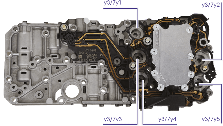
| Actuator | Function |
|---|---|
| Y3/7y1 | Control valve “for 1st and 4th gear” |
| Y3/7y2 | Control valve “for 3rd gear” |
| Y3/7y3 | Control valve "for 2nd, 5th and “R” gears” |
| Y3/7y4 | Control valve for lock-up |
| Y3/7y5 | Shift valve |
Clutch Control
The labyrinth mounted underneath the TCU (=Transmission Control Unit) is equipped with several control valves and shift valves. By controlling the control valves (also known as solenoid valves), the fluid pressure can be directed towards these valves. This ensures that the valves are adjusted to the correct position. This allows fluid pressure to flow to the various multi-plate clutches. As soon as the clutch is engaged, the gear is engaged. In this regard, the 722.7 differs substantially from a manual gearbox.
A total of 5 control valves are used. As can be seen in the following diagram, control valve Y3/7y4 controls the lock-up clutch. The other valves work together to operate the other clutches (e.g. K1 = the clutch of gear 1):
Shift diagram
| Valve name | K1 | K2 | K3 | K4 | K5 | KR |
|---|---|---|---|---|---|---|
| Y3/7y1 via valves RS14 and SS14 | ≈ | 0% | 0% | ≈ | 0% | 0% |
| Y3/7y2 via valve RS3 | 0% | 0% | ≈ | 0% | 0% | 0% |
| Y3/7y3 via valves RS25R and SS25 | 100% | ≈ | 100% | 100% | ≈ | ≈ |
| Y3/7y4 Lock-up clutch | ≈ | ≈ | ≈ | ≈ | ≈ | 0% |
| Y3/7y5 Shift valve | 100% | 100% | 100% | 0% | 0% | 100% |
Similar control valves

4 of the 5 control valves in this Mechatronic are of the normally closed solenoid type. This means that the valves are closed when de-energised and do not allow any liquid to pass through. This means that control valves Y3/7y1, Y3/7y2,Y3/7y3 and Y3/7y4 can be exchanged without penalty.
Valve Y3/7y5 is another case. This is not a control valve, but a shift valve: the valve can only be opened to the maximum or closed to the maximum. In addition, this valve works with a different voltage.
In case of unusual shifting complaints:
The shift diagram can also be used for diagnostic purposes. If, for example, the car does not want to shift to 3rd gear, this could be due to clutch K3, but of course also to a defective control valve. In this case, Y3/7y2 is the valve that has to be additionally switched. By changing the position of this control valve, the complaint (and corresponding error codes) should move to the new position. Unfortunately, the control valves cannot be extensively tested using diagnostic software.
The TCU in detail
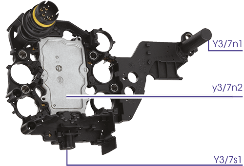
| Sensor | Function |
|---|---|
| Y3/7n1 | Speed sensor |
| Y3/7n2 | Control module |
| Y3/7s1 | Starter lockout |
This type of TCU is relatively simple: 1 plug, 1 speed sensor, 1 switch for the starter lockout and 1 central control module. Communication with the rest of the vehicle is completely via CAN. As a result, the plug only needs 5 connections. The speed sensor uses the Hall principle: a change in the magnetic field generates an electronic signal. This signal can also mimic itself.
Limp mode
After the TCU has detected an electrical fault or measures an unexpected coupling pressure, it will always activate the limp mode. The electronic part of the Mechatronic is completely switched off. This means that all control valves are in a Voltage-Free State. This will increase the overall working pressure to the maximum value, the lock-up clutch will disengage and the gearbox will shift to 5th gear and stay in it (the only gear that can operate with 0% pressure from all valves).
It is still possible to shift to “2” and “R” in a limp mode: leave the selector lever in “P” for 10 seconds before selecting “D” or “R” when the vehicle is stationary.
Check the sensor function yourself
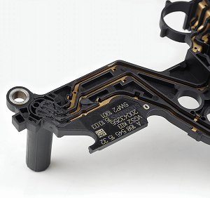
If the car from which the TCU comes is still available, the speed sensor of the extended TCU is quite easy to check by yourself. The only condition is that a diagnostic tool is needed to make live data visible.
Proceed as follows:
- Connect the connector from the car to the separate TCU
- Turn on the ignition (power supply)
- Find the required live data in the reader
- Use a magnetic screwdriver to move along the sensor several times
The frequency at which the screwdriver passes the sensor now becomes visible as the speed.
N.B.:
If live data are not available, the operation can also be measured via the copper tracks at the rear of the speed sensor. Use a multimeter for this. Between track 1 and track 3, the voltage will change between 0 volts and 5 volts each time a magnetic screwdriver is moved past the sensor.