 da
da de
de es
es fr
fr it
it nb
nb nl
nl pt
pt sv
sv fi
fiVDO ECU Mercedes-Benz A-Class (W168)

Because cars are packed with comfort and safety features these days, it’s getting increasingly difficult to fit in every little component. It isn’t likely to get any better in the near future, especially under the bonnet, so manufacturers are starting to look for clever solutions. Maybe that’s why VDO / Mercedes-Benz questioned : Why would you fit the ECU (Engine Control Unit) and AFM (Air Flow Meter) separately, when it’s possible to combine them into one single component?
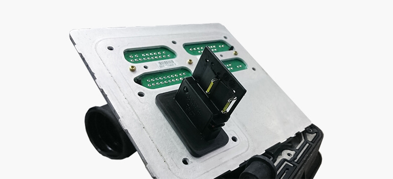
And that’s exactly what has been done in the Mercedes A-Class. Maybe the odd shape of this ECU (which seems directly melted onto the air intake) looks a little confusing at first glance, but in reality it really does save you space. Furthermore, both the air intake and the ECU need stable conditions with constant low temperatures, so this configuration also makes it a lot easier to create the overall layout of the engine bay : You’ll only need one area with low temperatures, because the air intake and ECU are literally fused into one part. So far this configuration has no down sides.
What’s causing the main malfunctions?
But what if either the ECU itself or the air flow sensor fails? Unfortunately this delicate air flow sensor is also the weakest link of this combined ECU. The most common complaint is stalling of the engine at idle, but also complaints such as power loss and odd O2-sensor readings are very common.
In almost every case all these symptoms are the result of a faulty AFM. What most people don’t realise while diagnosing the complaint, is even if the faulty AFM still seems to work, the sensor could still be the source of all problems. In some cases the air flow sensor slowly loses its accuracy. Once this symptom occurs, the measured air flow does not match the reality anymore. The ECU then makes a miscalculation that as aresult causes a wrong air/fuel ratio.
This is basically what makes diagnosing a defective AFM extremely difficult : A defective AFM may not always trigger fault codes, but that doesn’t mean everything works properly. Even if the AFM does trigger fault codes, the readings could still be quite confusing. You will often encounter fault codes relating to ignition, injection and air/fuel ratio. That’s why we’ve compiled a list for you, just to show you what may indicate a faulty AFM:
- P0100 Mass or volume air flow, implausible signal
- P0101 Air mass sensor, implausible signal
- P0102 Air mass sensor, signal too low
- P0103 Air mass sensor, signal too high
- P0104 Air mass sensor, sporadic interference
- P0129 Barometric pressure too low
- P0130 Oxygen sensor, circuit failure in Bank 1 – Sensor 1
- P0136 Oxygen sensor, implausible signal in Bank 1 – Sensor 2
- P0169 Fuel mixture not right
- P0170 Fault in system, fuel mixture adjustment
- P0171 Composition air / fuel mixture too lean
- P0172 Composition air / fuel mixture too rich
- P0173 Incorrect calculation air / fuel mixture in Bank 2
- P0174 Air / fuel mixture too lean in Bank 2
- P0175 Air / fuel mixture too rich in Bank 2
- P0176 Fuel mixture Sensor fault circuit
- P0177 Fuel mixture sensor , implausible signal
- P0178 Sensor fuel composition , signal too low
- P0179 Fuel mixture sensor, low input
To be honest, these fault codes are just a few examples of the fault codes that may appear. All fault codes from P1000 to P1999 are specific codes which have different meanings depending on which car manufacturer uses the ECU. Therefore we can assume there will also be fault codes relating to a faulty AFM in these ranges.
Remanufacturing: the process
“Just replace the air flow meter and we’re done, right?” You might think this once you’ve read the above information. However, there’s a bit more to it… The AFM is directly mounted onto the PCB of the ECU itself. What also needs to be taken in to consideration is ACtronics has a strict policy to solve problems and not to simply replace a defective part.
Fun fact:
Mercedes-Benz also noticed the complaints regarding faulty air flow sensors. Because of this, you won’t find the combined ECU’s anymore in cars that are built from 2001 onwards. Mercedes-Benz replaced the old VDO ECU’s and fitted the AFM’s separately. This new solution makes it possible to simply replace an air flow meter whenever it’s defective.
So, what are we doing?
The remanufacturing process begins with the dismantling of the outer shell. The plastic tube in which the AFM is located usually contains quite a bit of oil. Even a tiny amount of oil can damage the air flow sensor.
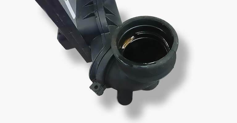
Therefore, this tube will be replaced with a clean one from our stocks. We also check if all seals are intact and replace them if needed.
Once we’ve opened the combined ECU, we focus on the AFM. The first thing we have to do is replace the two sensors on the outside of the AFM. We never opt for the widely available imitation sensors because it’s essential to use sensors with the same quality as OE (Original Equipment) in order to ensure longevity and accuracy. That’s mainly why we are very proud to tell you that we are using exactly the same sensors as Mercedes-Benz themselves. These sensors are very difficult to obtain, but ACtronics has found a reliable source.
Even after replacing these sensors, the remanufacturing process has not been completed. We also open the sensor housing in order to replace various components on the tiny PCB with new (better) ones. Once that process is complete, we assemble a new self-made cover. This extra step makes the remanufactured product better than OE and that’s exactly what distinguishes us from other repair solutions.
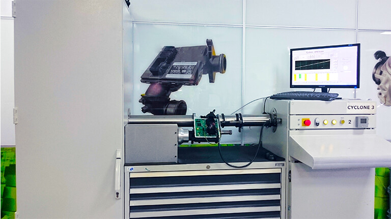
Once the remanufactured AFM is installed back onto the PCB, the testing and fine-tuning begins. We have access to a sophisticated testing environment that was completely builded and developed by own R&D team. We call it the “Cyclone”. The system actually blows air through the air mass meter to mimic the operation while driving. This realistic simulation enables us to adjust the remanufactured AFM with high accuracy. We use a small potentiometer in order to adjust the deviation within 0,03V. We know it would be a lot easier to simply copy the values of another AFM, but this doesn’t give us the level of quality and accuracy we want. Each product has to be absolutely perfect. That’s also the reason for keeping up the development of our remanufacturing method, hence the Cyclone that we’re currently using is 3rd generation already.
The result of this whole process is an ECU with an AFM that functions better and more accurately than the original. “Better than OE” is more than just a slogan for us, we do everything we can to deliver that promise. So let’s be honest now, would you still consider buying a new ECU, which costs well over £ 500,- or would you rather choose our cheaper and better option?
The ECU in detail
It should be clear by now that the option of mounting the AFM directly onto the ECU wasn’t a smart choice. This configuration makes it impossible to simply replace the AFM and although a direct connection of the AFM onto the PCB is less susceptible to interference than a conventional separate sensor, it could also be a major disadvantage. The AFM has proven to be sensitive and often causes malfunctions and therefore simple replacement should be possible.
But fortunately the ECU itself has no further surprises. All there is to see, is a relatively simple PCB with two large connectors. As with almost any ECU connectors, they are intentionally shaped differently in order to prevent the wiring harness from being connected incorrectly. The outer housing isn’t equipped with cooling fans. However, malfunctions with regard to high temperatures haven’t been observed so far. Apparently, the architecture of the ECU and the position in the engine bay are both well thought out.
Besides the input from the AFM, the VDO ECU also obtains inputs from various other sensors. It’s really important to gather as much information as possible in order to make right decisions about timing for both ignition and injection. The following graphic shows you several sensors that transmit values to the ECU.
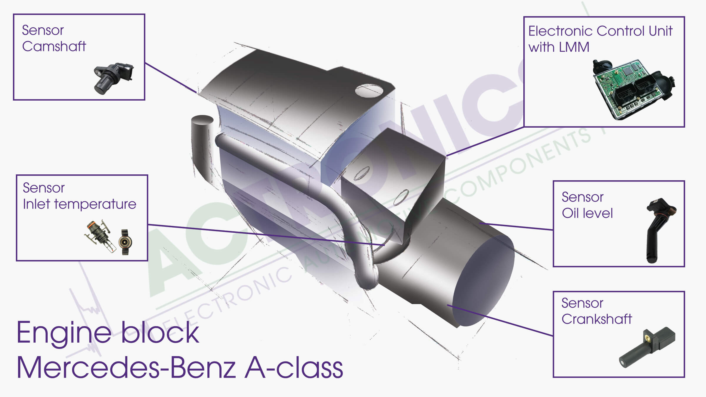
After obtaining all of this information the ECU can now generate the right outputs for controlling ignition and injection:
The Mercedes-Benz A140 has one combined coil that can actuate all spark plugs. The ECU uses two different signals for this operation.
The injection system on the A140-engine is equipped with one single injector rail and four individual injectors that are each controlled separately by the ECU. This engine however doesn’t make use of direct injection. The actual injection takes place into the inlet manifold.
Everything the ECU needs to compute (base maps, calculation models and so on), is stored in a flash memory. The main processor uses all inputs and all stored data to generate the required outputs. These outputs will then be sent to the right actuator.
Disassembly of the ECU
We always recommend use of the official manufacturer’s instructions. The following text is for guidance only.
The VDO ECU in the Mercedes-Benz A140 is hidden under a large cover on the right side of the engine block. The cover is secured by three screws. In order to remove the lower screw, the long inlet tube on the front of the engine has to be removed first. Once both the tube and the cover are removed, the VDO ECU becomes visible. It’s wise to release the two large connectors at the rear of the ECU before it becomes completely disassembled. After this is done, it’s just a matter of unscrewing both pipes on the side of the ECU. You can now remove the ECU from the car.