 da
da de
de es
es fr
fr it
it nb
nb nl
nl pt
pt sv
sv fi
fiSteering & Acceleration Sensors Guide
The steering angle sensor is usually mounted exactly where you would expect it to be: behind the steering wheel, around the steering column. Every now and then, a manufacturer decides to place the sensor close to the steering rack, but this is quite rare. Several types are in use. The Hall-effect type is the most popular, but versions with sliding contacts are also still common. There are also digital optical sensors that generate a specific signal based on the rotation angle measured at that moment. We will briefly run through the differences between these types.
Analogue with sliding contact
The analogue steering angle sensor comprises two potentiometers, also called voltage dividers. These voltage dividers use a fixed resistive track, often made of carbon, through which the voltage passes. A moving sliding contact moves along this resistive track and the position the contact is in at that moment determines how much voltage is passed. There are versions that work with a reference voltage of 5 volts and versions that use 12 volts. The second voltage divider is not a control device. It is used to determine the direction of rotation of the steering wheel: to the left or right. By orienting the voltage dividers in opposite directions, the difference between the two voltages can be used to determine whether the steering wheel turns clockwise or anti-clockwise. The voltage output in the zero position (when the steering wheel and wheels are straight) can vary from one voltage divider to another. This is done on purpose to check that the steering angle sensor is functioning correctly. Many variants of this type of steering angle sensor are available now, so unfortunately we cannot state specific values.

The sliding contacts may wear to the point where permanent contact is no longer possible. This is the reason why sliding contacts are used less and less in the automotive industry. So if a steering angle sensor of this type fails or loses its signal every now and then, check its sliding contacts first.
Hall-effect
Hall-effect steering angle sensors (such as the Bosch LWS5 and LWS6) are non-contact devices and therefore not subject to wear. As is the case with active wheel sensors, this steering angle sensor uses a multi-pole ring. The Hall-sensors (plural: there are several of them) detect each movement to an accuracy of 1.5 degrees and generate block signals that are sent to the control unit. As the phase of the signal from each Hall sensor is different, the direction of rotation can be determined immediately and it is also obvious that the sensor is working properly. What follows is a calculation based on the actual steering angle, the direction of rotation and speed of rotation. The result is converted into a CAN signal and sent directly to the ESP ECU.
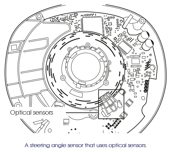
Optical
Mercedes-Benz in particular was a big fan of optical steering angle sensors for a while. This type of sensor also generates multiple block signals, but instead of magnetism it uses light. By using multiple tracks, each with its own hole pattern, different signals are created. These signals are compared by the controller and the result is converted into a usable digital signal.
On the face of it, you would think that this type of sensor actually works just as well as a Hall sensor. However optical sensors have one formidable enemy: dirt. A few specks of dust can be enough to block the light beam and disrupt the signal. So optical sensors are only really suitable for a fully enclosed environment.
In the event of a fault with an optical sensor, always check first for dust and other dirt. Blowing away this dirt may be enough to solve the problem!
Calibration
Calibrating the steering angle sensor is a very simple job with the help of good diagnostic equipment. In many cases, one full turn to the left and right is enough to fully calibrate the sensor. There are also self-calibrating sensors. With the ignition switched on, one full turn to the left and right is sufficient. In many cases, the ESP system can also autonomously detect whether calibration is required by comparing the values of the steering angle sensor with those of the various acceleration sensors. If the system detects that the car is driving continuously in a straight line and that the steering angle deviates excessively, the ESP system will deactivate and the warning light will come on.
Electric power steering
The steering angle sensor is not only used as a control input for the ESP system, it is also linked to the electric power steering. An electric motor provides power assistance for the steering movement as soon as a change in steering angle is detected. This makes hydraulic power steering superfluous. The compact size and low weight of this system are not the only advantages; it can also be used to adjust the steering system. For example, it can be set to a comfortable or a sporty setting. It can also be very handy when parallel parking: e.g. Fiat’s 'city’ button, which makes the steering feel extremely light. One disadvantage of electric power steering is the lack of feel: because the electric motor determines the movement, the reactions of the wheels on the road surface can hardly be felt at the steering wheel.
BMW 3 series E90: brief DSC error messages
Suppose: every now and then a DSC message briefly appears on the dashboard, but it disappears just as suddenly as it came. Reading error codes out does not work, because the error is not saved. Still, the message comes back every now and then. So, what do you do? The only option you have is to check everything that can cause intermittent complaints. A tip that we can give in the case of the BMW 3 series E90: check the steering angle sensor. There are several known cases where the steering angle sensor was so badly weathered that it caused these complaints. We don't know why this is so specific to the E90.
Acceleration sensors
In addition to the steering angle, the 'ESP ECU' also needs real-time values that tell it how the vehicle is moving. This is what the acceleration sensors are for. These sensors can be grouped in two categories: the lateral acceleration sensors and the yaw rate sensors. However, in practice you will hardly ever find these sensors as separate units: both Continental and Bosch have built them into a single housing. We will take the sensor used for the slightly older Bosch 5.7 ESP system as an example in order to explain operation.
Calibrating ESP sensors
Important for systems with ESP: after installation, all ESP sensors must always be recalibrated. The better universal diagnostic equipment will have this function available. If not, malfunctions are guaranteed.
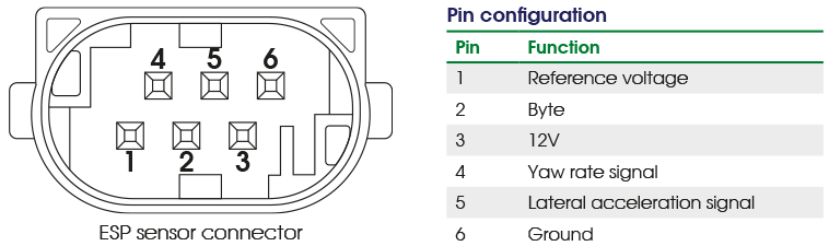
The ESP sensor uses a power feed (12V), ground and a byte (block signal, 0 – 6.8V). The byte is used as a control and is retransmitted together with the output signal from the yaw rate sensor. The yaw rate sensor also uses a reference voltage (2.5V). The yaw rate sensor will influence this reference voltage positively or negatively: positively for a positive yaw angle, negatively for a negative yaw angle. As a result, the output varies from 0.7V to 4.3V. Because the control byte influences this signal, the output signal should look like this:
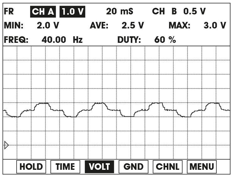
NOTE: If the signal is linear, the sensor is defective!
The lateral acceleration sensor does not use the reference voltage and the control byte. The output signal is linear and ranges from 0.5V to 4.5V. A gravitational force of -1.5 G or +3.5 G is required to reach these values.
Evolution
While the preceding explanation gives us a good understanding of how ESP sensors work, a lot has changed since then. Like all the other electronics in vehicles, ESP has slowly switched from analogue signals to CAN messages. After all, a single central network offers many advantages. To give two examples: the signal is available throughout the vehicle and far less wiring is required. This saves space and reduces weight.
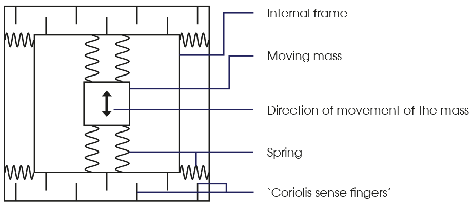
The technology in the sensors themselves has also improved. When we compare the Bosch 5.7 ESP to the Bosch 8.0 ESP, we see clear differences. Both the lateral sensor and the yaw rate sensor now use piezoelectric material that generates an ever-increasing voltage as the acceleration force increases:
A sprung mass is located in the middle of the piezoelectric material. As soon as the car accelerates or turns in a certain direction, the mass follows suit. The force required to move this mass from its resting position generates a specific voltage in the piezoelectric material. As you have probably guessed, this voltage increases the more the mass is moved out of its resting position.
This voltage is then converted into an electrical signal. When a calculation is applied to the values for the lateral acceleration and the rotational acceleration, the movement of the car can also be evaluated against the steering angle.
Useful to know:
The more recent generation of yaw rate sensor is also known as iMEMS, which stands for ‘integrated Micro Electro-Mechanical System’. Thanks to this technology, the yaw rate sensor is now small enough to be integrated into the ECU without difficulty. Modern ABS ECUs, like some types of the ATE Teves MK60E, do not need ESP sensors anymore.
You need to consider this when tackling ESP malfunctions: the fault can also be located inside the ECU nowadays.
Error code 01423 - Yaw rate sensor
In case of incorrect basic setting / adaptation: perform the basic setting again. In case of electric circuit failure: check the wiring to the yaw rate sensor (G200) and check the supply voltage to the sensor. Everthing allright? Then replace the sensor. If the error code is still present after replacing the sensor, please contact our Customer Service.
Active Steering
Cars equipped with Active Steering, such as BMW and Mercedes-Benz, have two ESP sensors: a primary sensor under the driver’s seat and a secondary sensor under the passenger’s seat. The secondary sensor is largely identical to the main sensor, but has a terminating resistor (the primary sensor does not) and also uses a different CAN ID. So these sensors are not interchangeable. The way in which both sensors are used by the ESP system is also very different. The values from the secondary sensor are used purely as a check to validate the values from the primary sensor. So the secondary sensor cannot take over the function of the primary sensor. If a difference is measured between the two sensors, the system switches to fault mode. Both sensors operate passively: a signal is only sent when the ESP ECU requests it. Not a problem because, as mentioned earlier, this takes place every 10 milliseconds.