 da
da de
de es
es fr
fr it
it nb
nb nl
nl pt
pt sv
sv fi
fiHella Turbo Actuator

The principle of a turbo compressor is actually quite easy, but it might be a good idea to keep its power under control. Without any form of pressure control, the turbo will keep blowing air into the engine which is not always desirable. It might even lead to serious damage to the engine in some cases. In an ideal scenario, one would want to continuously adjust the turbo pressure to the current circumstances. Luckily there are turbo actuators that are able to do this, but what does such a turbo actuator do exactly? And maybe even more interesting: what happens when it becomes faulty?
What becomes defective in most cases
Let’s start with the defects we encounter. As told before, many things can become faulty when the pressure is not controlled correctly. After all, not everything in the engine could withstand (a too) high air pressure and (too) high temperatures. Fortunately, the system is controlled in such a way that the ECU of the engine ensures a safe switch to emergency mode once an incorrect pressure is measured. A defective turbo actuator does not cause more damage to the engine but only causes error codes and less power. The saved error codes will often show that there is indeed something wrong with the turbo or pressure control:
- P0234 – Engine Overboost Condition
- P0299 – Turbo/Supercharger Underboost
- P2263 – Turbo/Supercharger Boost System Performance
Many brands have their own specific error codes, like Ford for example:
- P132A
- P132B
However, imagine that the turbo is in working order, then what could become defective in the actuator itself?
We will explain more about the functioning of the control unit later, but we can already reveal that the actuator basically consists of an electric motor, a plastic worm gear and a printed circuit board. Unfortunately, we observed multiple weaknesses in each of these components, however, just about all defects are repairable. Repairing (or better say: remanufacturing) is also no problem, even though car manufacturers would like you to believe the opposite. They seem to be keen on selling a completely new turbo to the customer, while these actuators are rarely available as separate parts.
Remanufacturing: the process
We look at a turbo actuator as a mechatronics component: consisting of both mechanics and electronics, meaning that the remanufacturing process also has two phases.
The mechanical defects are processed by our Mechatronics Department. Our in-house developed components are equal to or better than the original, enabling us to guarantee high quality. We do not only go through defective components but always take care of all weaknesses. This involves preventively replacing all moving elements in order to guarantee the quality of the remanufactured product.
Complaints about electronics are processed by our Bonding Department. This department has high-value equipment that is able to install new connections on and to the printed circuit board in a very accurate way. This method is called (wire) “bonding” and attaches new connections to the existing contacts by means of ultrasonic vibrations. It is surprisingly accurate and components on the printed circuit board are not exposed to heat, which is a major advantage compared to soldering. It enables us to guarantee a quality that is much higher than that of components that were repaired by soldering. However, it must be mentioned that bonding is not always the best choice for creating new connections. Soldering might be preferred in certain situations. We will soon post an article about that.
After repairing, we always conduct a final test. Our test setup enables us to simulate every signal coming from the ECU. We do not only test whether everything runs smoothly but we are also able to check if electronics on the printed circuit board function like they are supposed to. The test equipment is even able to measure torque and position. So after the test, we are absolutely sure that the remanufactured product functions at least as good as an original one.
Fun detail: the test equipment has been designed and developed by ourselves. This does not only reflect our specialist approach but also our expertise on the topic.
The Hella Turbo Actuator in detail
Technicians and turbo specialists probably think of the following explanation as too short-sighted (and right they are), but a turbo can briefly be described as a turbine and compressor wheel together in one casing. The turbine wheel at the outlet side starts spinning once exhaust air blows alongside. A shaft transfers the rotation to the compressor wheel at the inlet side; also causing this side to rotate. In turn, the special shaped vanes start to “push” air into the engine. The higher the speed of the wheel, the higher the pressure of the air moved into the engine.
This is also exactly the problem: a turbo does not know how to stop. It would be much better if the exhaust air supply could be controlled in such a way that the correct amount of thrust is generated at all times, instead of solely depending on the engine speed and the position of the throttle valve. Fortunately, various technicians put their heads together and came with the following solution: turbo compressors with variable geometry. This new turbo uses adjustable vanes around the central rotating turbine wheel at the outlet side. By adjusting the position of the vanes with a setting ring, the amount of exhaust gas can be changed. Problem solved!
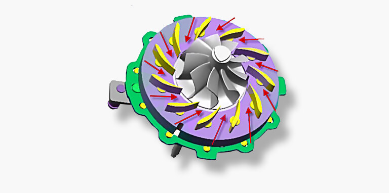
Well, solved… not entirely. The variable vane system only consists of mechanical parts so it cannot operate itself. This is why turbo actuators were developed: they can pull the lever that controls the adjustable vanes. Turbo actuators can broadly be divided into three categories: pneumatic actuators, electric actuators and hybrid actuators. Though, only electric and hybrid actuators come with variable geometry, which is why we will not explain the technique of pneumatic actuators.
Electric actuators
Electric actuators are designed to respond to the electric input coming from the ECU. The extent to which the vanes are adjusted therefore depends on the decisions of the ECU. The ECU contains all sorts of information such as engine temperature and inlet pressure, but can also respond to inputs from options like the adjustable driving mode (such as neutral, dynamic, sport). This is especially interesting for car manufacturers since it offers more settings like a lower turbo pressure when the engine is cold or a slightly higher turbo pressure once the sports mode is activated. That is also why we often see electric actuators in vehicles with modern turbo engines. Audio, BMW, Citroën, Ford, Jaguar, Mercedes-Benz, Peugeot, Volvo, VW… they all use the Hella electric actuator, often in combination with a Garrett turbo.
Did you know?
The vanes of a VGT (turbo compressor with variable geometry) can become stuck due to carbon deposits. This does not only influence the system’s functioning but could also damage the turbo actuator. Therefore, always check whether the vanes of a VGT can move freely once a turbo actuator becomes defective. Do this to prevent that the new actuator gets overloaded. Checking this can best be done by disconnecting the bar from the lever and then moving the lever back and forth.
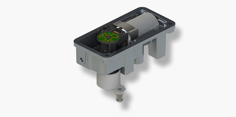
As explained before, the Hella electronic turbo actuator basically consists of an electric motor, a worm gear and a printed circuit board. The input from the ECU is processed by the printed circuit board and gives the electric motor a signal to rotate clockwise or anti-clockwise for a certain period of time. This causes the worm gear to move the lever of the VGT to the desired position. It does not have to completely open or closed since the setting can be adjusted anytime, by changing the position of the lever.
There are two kinds of Hella turbo actuators: a REA (Rotary Electronic Actuator) and a SREA (Simple Rotary Electronic Actuator). Both versions use a 5-pin plug. However, the pin usage differs:
SREA:
- Engine rotating clockwise
- Engine rotating anti-clockwise
- Mass
- 5V PWM-signal (1 kHz)
- 5V
REA
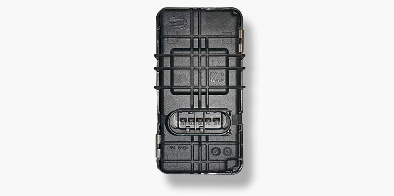
- 12V
- Mass
- CAN-L
- 5V PWM-signal (1kHz)
- CAN-H
Apart of the pin assignment, both types differ in more ways, such as the way in which the position of the lever is determined and adjusted. The SREA receives a signal through square wave to pin 1 or 2 with the order of letting the electric motor run for a while. This causes that the lever puts itself in the right position. The REA, however, uses a CAN message to determine which action is necessary. The current position of the lever is measured on the printed circuit board and the sensor that does this is called a C.I.P.O.S. sensor. This value is compared to the desired value and if needed, the electric motor is operated to move the lever into the correct position. This may seem cumbersome but also has its advantages. For example, the position of the lever is always known and possible deviations can be filtered out. Even more, the ECU can use the lever position as input for actions or calculations. This makes the entire system a lot more dynamic.
Hybrid actuators
Turbos with variable geometry that do not use the electric Hella turbo actuator also exist. These are partly pneumatically controlled, just as certain Fiat JTD engines. But why was this chosen? There are situations where one would want to use electric actuators but where that is simply not possible. For instance due to a lack of space or because of the configuration of the turbo that is going to be used. Other solutions are then needed and that is why hybrid actuators were developed.
Although its name gives the impression that it is only about one component, the hybrid actuator actually consists of an “old-fashioned” pneumatic turbo actuator and a small electronic adjustment valve, controlled by the ECU. The pneumatic actuator uses the overpressure in the inlet process to set the adjuster ring of the vanes. This setting is however manipulated by the small electronic adjustment valve. A signal from the ECU adjusts the valve to a more closed or opened position so that the pneumatic turbo actuators receive less or more overpressure from the inlet. By varying this position, one can determine how the lever is controlled and be able to control the position of the adjustable vanes.
To be honest: the system is less accurate and dynamic than Hella’s REA but works fine as an alternative. The electric adjustment valve is in this system not only smaller in size than the complete Hella turbo actuator, but also enables using turbo compressors where application of Hella turbo actuators is not possible due to configuration. Besides, the electronics in this system are farther away from the large temperature fluctuations around the turbo compressor.
A hybrid actuator can be a good alternative, especially in engines where heat is less easily disposed. We can imagine that, in certain situations, a car manufacturer chooses the alternative solution instead of the Hella turbo actuator.
Disassembling the unit
The biggest problem during disassembly is most probably the accessibility of the Hella turbo actuator. This differs per car. Once enough space is created, it would not be difficult for the trained technician to disassemble the actuator. First, the plug and the lever of the VGT must be disconnected. The lever is locked with a circlip. Once this is done, only three bolts need to be loosened in order to detach the turbo actuator from the turbo.
Pay attention to the following when assembling:
Some moving space was created at the 3 three bolts that hold the turbo actuator. This means that you cannot tighten the actuator “randomly” or with some “luck”. Refer to the car-specific documentation for instructions regarding the correct setting and alignment.