TCU DSG7 DQ200
After the success of the DSG 6, a successor was inevitable. Having said that, a DSG 7 gearbox can’t really be called a successor. This newer DSG version uses a dry clutch and can handle a bit less torque than its older brother.
So why did Volkswagen AG make this choice? The answer can be found in weight and resistance. With regard to the environment and fuel consumption, the DSG 7 is the better option, as long as it doesn’t require too much torque, that is.
Complaints and error codes
Known complaints
- The gear shift indicator (“PRNDS”) on the dashboard will flash
- The gearbox does not shift
- Short circuit: 30A fuse melted
- Leakage and / or pressure loss
Can be remanufactured
| OBD II | VAG | Description |
|---|---|---|
| P0562 | VAG | System voltage, voltage too low |
| 16946 | 17099 | Sensor / pressure switch transmission fluid pressure A, Unlikely signal |
| P0841 | 17225 | Control module defective |
| P1604 | 8012 | Hydraulic pump system, supply voltage too low |
| P177F | - | Hydraulic pump system, overload protection |
| P17BF | - | Functional limitation due to pressure drop |
| P1895 | 18303 | Functional limitation due to insufficient pressure |
| P189C | - | No communication with TCM |
Remanufacture may be possible (additional diagnosis required)
| OBD II | VAG | Description |
|---|---|---|
| P173A | - | Position sensor 1 for Gear Selector, unlikely signal |
| P173B | - | Position sensor 2 for Gear Selector, unlikely signal |
| P173C | - | Position sensor 3 for Gear Selector, unlikely signal |
| P173D | - | Position sensor 4 for Gear Selector, unlikely signal |
Check the position sensors and the corresponding magnets for contamination by metal particles. If there is any contamination, check the gearbox thoroughly for mechanical wear/damage. Then clean the sensor and check that the error code is still present. If this is the case, then it is still plausible that the TCU is defective and needs to be remanufactured.
Can´t be remanufactured
| OBD II | VAG | Description |
|---|---|---|
| P072A | - | Neutral not selectable |
| P072B | - | Reverse gear not selectable |
| P072C | - | 1st gear not selectable |
| P072D | - | 2nd gear not selectable |
| P072E | - | 3rd gear not selectable |
| P072F | - | 4th gear not selectable |
| P073A | - | 5th gear not selectable |
| P073B | - | 6th gear not selectable |
| P073C | - | 7th gear not selectable |
Check the position sensors and the corresponding magnets for contamination by metal particles. If there is any contamination, check the gearbox thoroughly for mechanical wear/damage. Then clean the sensor and check that the error code is still present. If this is the case, then it is still plausible that the TCU is defective and needs to be remanufactured.
General operation DSG 7
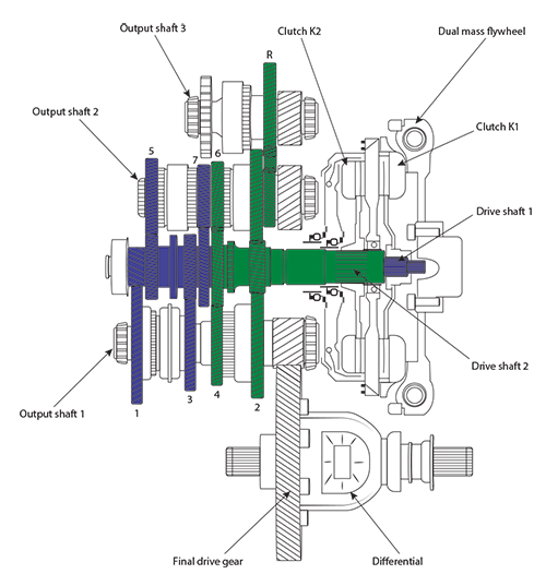
The DSG 7 gearbox is an automatic double clutch gearbox. DSG stands for “Direktschaltgetriebe” or “Direct Shift Gearbox” and the 7 indicates that there are seven forward gears. For this gearbox the designation ‘DQ200’ is also used. The Q (‘Quermotor’) indicates that this gearbox is used for transverse engines.
Mechanically, the DSG 7 gearbox can be described as a manual gearbox with two dry plate clutches, two drive shafts (input, primary) and three output shafts (secondary). An electronically controlled hydraulic control (Mechatronic) ensures that the gearbox can operate fully automatically. As an option, an additional manual shifting option can be selected (Tiptronic).
Automatic gearbox
A dual mass flywheel connects the crankshaft of the engine with the drive plate that rotates in line with the crankshaft. Two dry clutches on either side of the drive plate rotate independently of each other around the same shaft and each drives its own drive shaft by means of a ‘spline shaft’. Drive shaft 1 rotates inside the hollow drive shaft 2.On drive shaft 1 are the gears for 1st, 3rd, 5th and 7th gear. The gears for the 2nd, 4th, 6th and reverse gear are on drive shaft 2. From drive shaft 1, the gears for 1st and 3rd gear are driven on the first output shaft and the gears for 5th and 7th gear are driven on the second output shaft. From drive shaft 2, the gears for 2nd and 4th gear are driven on the first output shaft and the gears for 6th and reverse gear are driven on the second output shaft. Sprocket R1 on the second output shaft drives the third output shaft for reverse gear via sprocket R2. All three output shafts drive the differential gear.
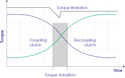
Because the gears for 1st, 3rd, 5th and 7th gear are on drive shaft 1 and the gears for 2nd, 4th, 6th gear on drive shaft 2, shifting takes place from one drive axle to the other when shifting to the next gear. The next gear is already engaged on the corresponding output (main) shaft. When shifting gears, the clutch to the drive shaft of the ‘old’ gear is decoupled in one smooth movement and the clutch to the drive shaft of the ‘new’ gear is coupled in one smooth movement. So there is an overlap in the drive through both gears. In addition, when shifting up, the engine torque is slightly lowered, while when shifting down, the engine torque is slightly increased. All in all, this ensures a fast and smooth shifting action with no noticeable interruption in propulsion.
The mechatronic in detail
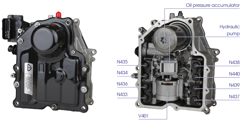
| Actuator | Function |
|---|---|
| N433 | Shift valve for shifting 1st and 3rd gears |
| N434 | Shift valve for shifting 5th and 7th gears |
| N435 | Pressure control valve for clutch K1 |
| N436 | Pressure control valve for system pressure in gearbox half 1 |
| N437 | Shift valve for shifting 2nd and 4th gears |
| N438 | Shift valve for shifting 6th and reverse gears |
| N439 | Pressure control valve for clutch K2 |
| N440 | Pressure control valve for system pressure in gearbox half 2 |
| V401 | Hydraulic pump motor |
Shifting, coupling and decoupling are controlled from the central gearbox control unit, the Mechatronic (J743). This consists of an electronic control device and an electro-hydraulic control unit. The Mechatronic is attached to the gearbox and has its own oil circuit, independent of that of the actual gearbox. This means that the hydraulic part of the DSG 7 DQ200 has its own oil pump, valves and cylinders. These cylinders are directly connected to the shift forks and the clutch levers.
The electro-hydraulic control unit incorporates an electrically driven V401 hydraulic pump and an oil pressure accumulator, which together ensure that the system pressure in the control unit remains between 40 and 60 bar.
The electro-hydraulic control unit has eight control valves. Valves N433, N434, N437 and N438 operate the shift forks that engage the gearwheels on the output shafts. Control valves N435 and N439 operate both clutches. Valves N436 and N440 regulate the required system pressures in both gearbox halves:
Control valve N436 controls the pressure in gearbox half 1 for valve N435, which controls clutch K1, for valve N433, which controls the shift fork for 1st and 3rd gears, and for valve N434, which controls the shift fork for 5th and 7th gears.
Control valve N440 controls the pressure in gearbox half 2 for valve N439, which controls clutch K2, for valve N437, which controls the shift fork for 2nd and 4th gears, and for valve N438, which controls the shift fork for 6th and reverse gears.
The TCU in detail
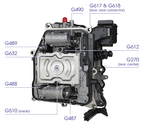
| Sensor | Function |
|---|---|
| G182 | Speed sensor input shaft gearbox |
| G270 | Pressure sensor for the hydraulic pressure of the gearbox |
| G487 | Position detection sensor for the selector fork for 2nd and 4th gears |
| G488 | Position detection sensor for the selector fork for 1st and 3rd gears |
| G489 | Position recognition sensor for the shifting fork for 5th and 7th gears |
| G490 | Position detection sensor for the selector fork for 6th and reverse gears |
| G510 | Gearbox oil temperature sensor in the electronic control unit |
| G612 | Speed sensor for drive shaft 2 |
| G617 | Clutch path sensor for clutch K1 |
| G618 | Clutch path sensor for clutch K2 |
| G632 | Speed sensor for drive shaft 1 |
In order to provide the Mechatronic with the necessary information, the TCU receives information from a number of sensors. The overview alongside shows exactly what information is received. Almost all of these sensors are built into the Mechatronic. However, speed sensor G182 is located outside the Mechatronic.
The TCU not only receives the necessary information from its own sensors but also exchanges information with the various measuring and control devices in the car via the CAN bus, for example:
- E313-Gear selector lever
- J104-ABS (with EDL) control device
- J248-Control unit for diesel direct injection
- J285-Control unit for display instrument panel
- J453-Control unit for multifunction steering wheel
- J519-Control unit for electrical installation
- J527-Control unit for steering column electronics
- J533-Diagnostic interface for data bus
- J623-Engine control unit for diesel engines
Always check the three speed sensors for metal particles. If there is any contamination, check the gearbox thoroughly for mechanical wear/damage. Then clean the sensor

 da
da de
de es
es fr
fr it
it nb
nb nl
nl pt
pt sv
sv fi
fi