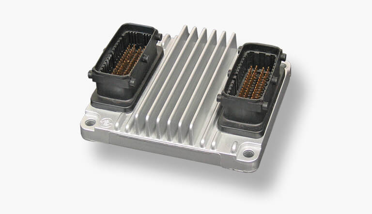
Delphi Delco Multec HSFI-2.x
“Multec? Aren’t they those ECUs (Engine Control Units) that are commonly used in Vauxhalls?” We’re not sure if it’s a good or a bad sign, but almost every car connoisseur we speak to, knows that many Vauxhalls are equipped with a Multec ECU. There’s an easy explanation for Vauxhall’s preference for Multec, rather than using a common Bosch ECU : Parent company General Motors (1929 - 2017) and Multec-manufacturer Delco Electronics have been working together for decades. You could almost look at Delco Electronics like it’s a sort of an American version of the German Bosch. Both companies actually have a lot in common. Delco Electronics was founded 1909 and became a well-known company in the late fifties thanks to its in-car stereo systems. Unfortunately the company went bankrupt and switched owners several times. Partly because of all this the ECU is now called Delphi Delco Multec HSFi-2.x.
But that one painful question remains… Why do so many people know the name “Multec” ? Are those ECUs really that bad? Multecs are indeed malfunctioning a lot, but this is due to several causes. It’s really a little too short-sighted to put the blame entirely on the ECU.
Lesson 1 :
When using car-electronics it doesn’t matter where and how you use the electronics, but always ensure utmost protection against moisture, temperature fluctuations and vibration. Maybe Vauxhall is also a little at fault in this matter? Mounting an ECU right on top of the inlet manifold simply doesn’t provide the best possible environment.
What’s causing the main malfunctions?
So, the ECU is operating in a hazardous environment full of vibrations and big differences in temperature. What could possibly go wrong? Several connections on the PCB (Printed Circuit Board) tend to tear or break and it’s no surprise for us to find these defects in every Multec we get hold of. So, it actually doesn’t matter which faults we find inside the ECUs, we always check all connections directly after every diagnosis. It’s really rare to have all connections on the PCB in perfect order. Almost every Multec will therefore continue to undergo our full remanufacturing process.
It’s probably no surprise that all these defects are causing so much trouble. The complaints we find on incoming Multec ECUs are also very diverse. Below we’ve made a short list of the most common complaints:
- Car doesn’t start, fuel pump isn’t activated
- Car doesn’t start, no injection
- Ignition fails on one or more cylinders
- Fluctuating RPM at idle
- Absolutely no throttle response
- Faults in EGR
- No communication to CAN
- Cooling fan isn’t activated
- And so on…

You’ll spot fault codes almost every time these complaints occur and they come in many forms. The fault codes that will appear while reading out the Multec always start with “P0? or “P1?, since a defect in the Multec ECU causes a breakdown in the powertrain of the car. A faulty ECU is specifically an engine problem; therefore the 3rd digit of the error code will always be a number between 1 and 5. All the other numbers are used for problems related to the gearbox or an optional hybrid drive.
The following possibilities remain:
- P01XX
- P02XX
- P03XX
- P04XX
- P05XX
- P11xx
- P12xx
- P13XX
- P14xx
- P15XX
When we look at our list with the most common error codes, this reasoning seems exactly right:
- P0105: Manifold Absolute Pressure / Barometric Pressure – Circuit
- P0230: Fuel Pump – Primary Circuit
- P0335: Crank Shaft Sensor – No / Faulty Signal
- P0340: Cam Shaft Sensor – No / Faulty Signal
- P0351: t/m P0354 Ignition Coils 1 t/m 4
- P1122: Accelerator Pedal Position Sensor 2<
- P1482: Fan Relay 2 – Electric Circuit Tiny Signal / Open
- P1483: Fan Relay 3 – Electric Circuit Tiny Signal / Open
- P1550: Electronic Throttle Control Reduced Power
Fun fact:
The Multec HSFI ECUs are also used in cars with diesel engines. There’s one malfunction that’s really standing out in these particular case s: fault code P0251 (Injection Pump Fuel Metering Control “A” Malfunction). If you ever experience this fault code on a Multec ECU that controls a diesel engine, please send in both the ECU and EDU (Engine Diesel Unit). In most cases it’s the EDU that’s causing this fault code, not the ECU itself.
Remanufacturing: the process
ACtronics doesn’t repair defects, but remanufactures products. We know for a fact that these ECU’s are very sensitive and we really want to be absolutely sure a remanufactured ECU will have the quality equal to or better than OE (Original Equipment). We therefore not only repair all complaints we encounter, but we also put each ECU through the complete remanufacturing process.
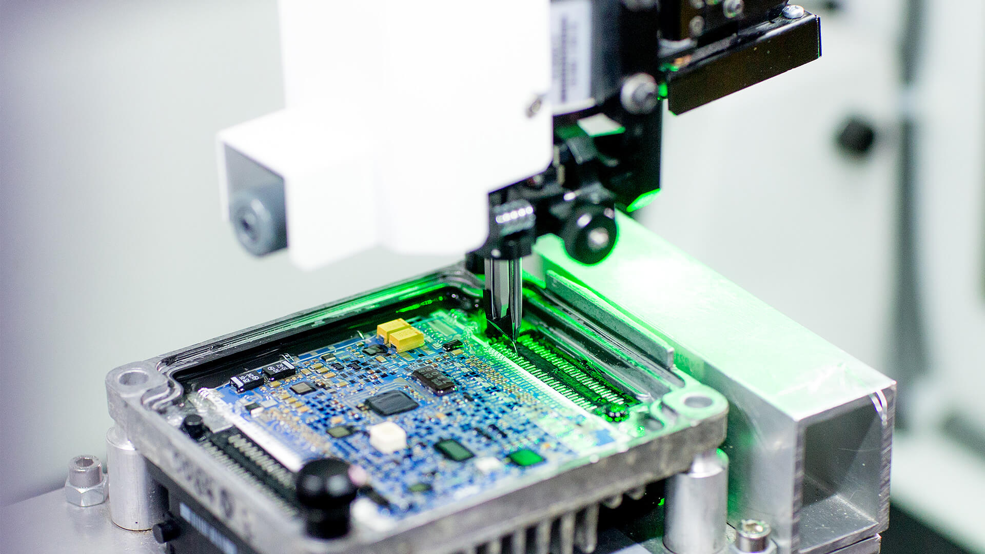
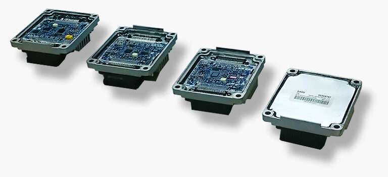
In this process the protective gel will first be removed professionally. Once all components are completely unprotected, we can begin with the removal of all existing bonding wires. This is a very delicate process, but this isn’t an issue thanks to our many years of experience. Once this second step is completed, all new bonding wires will be attached to the PCB using highly sophisticated equipment. The method we use is called “ultrasonic bonding”. The equipment is fully programmed and set up by our engineers and because of this we can also perform a pull test on the freshly installed bonding wires. This way we know for sure every new attachment is strong enough to withstand vibrations and fluctuations in temperatures. The newly made connections are even stronger than the original ones.

Once the bonding process is complete, it’s time for the final test. This test is necessary to establish if all the functions are working properly. Our testing facility also gives us the ability to perform an endurance test, in which the temperature actually rises in the ECU. You can really feel the ECU getting hot while performing this test. After this testing period a special high specification gel will be applied in order to properly protect the PCB and finally we will close the ECU with a new (self-developed) cap.
If the ECU still isn’t working properly after this entire process is complete, we will proceed using much more specific methods. There are many possibilities in the field of diagnosing and solving problems. In order to give you more insight into what may become defective, we will explain several components within the ECU in the next section.
The Multec HSFI-2.x in detail
A Multec ECU is easily recognizable by his appearance. Two large 64-pin connectors, indicated by the letters “K” and “M”, connect both sides of the circuit board to the main harness. It’s also relatively simple to find out what every pin is used for. This makes diagnosing quite straightforward.
But it quickly becomes more complicated once we look into the ECU itself. The PCB consists of several layers and is completely filled out with tiny components. These components are all used to support the main processor, which really needs more than just an EEPROM (Electrically Erasable Programmable Read-Only Memory) to operate correctly. But no worries, we’ll talk you through the main functions of the most important components.

Analogue to digital converters
Sensors such as airflow meters and O2-sensors are designed to generate a variable voltage that depends on the measured value. An ECU doesn’t understand this variable value, because the processor is designed to process digital numbers. For that reason, converters are installed to convert these voltages into digital 10-bit values.
Digital to analogue converters
Sometimes it’s necessary to have a digital value converted back to an analogue voltage. Certain actuators are able to vary the amount a valve will open and therefore an analogue input comes in handy. Digital to analogue converters ensure that these actuators can function properly.
Signal conditioners
Analogue values may come in different forms, but the converters always convert these values the same way into a digital number. They always use their own operating range of 0 to 5V. This could create some unusable values and therefore signal conditioners are installed onto the PCB. Simply put: the conditioners change all analogue values into a value that’s convenient for the converting process to execute correctly. The value of a O2-sensor for example, varies between 0V and 1.1V. But when a converter has an operating range between 0 and 5V, the degree of accuracy of the converted value won’t be ideal. In order to address this problem, the conditioner first increases the value 4 times. This way the converter works with values between 0V and 4.4V, which are preferable.
High-level digital output
ECUs nowadays are used for actuating all kinds of devices and components. The Multec ECU for example, actuates the cooling fan when necessary. These kinds of components often require a powerful input (relatively large Amps at 12V). But there’s one small problem: the delicate electronics in the ECU aren’t designed to cope with this. In order to solve this matter, a transistor (driver) is used. The transistor takes care of the powerful output that’s required to provide components with the right amount of power. But sometimes even a transistor isn’t enough. The cooling fan for example, requires such a large output that a transistor still won’t be strong enough. In that case, the output of the transistor is again used to actuate a relay.
Communication chips
These days cars are stuffed with all kinds of computers. The result of this broad network of components is multiple computers simultaneously trying to obtain the same signals at the same time. Therefore it’s necessary for computers to communicate with each other. For example, if the ECU detects a fault, then it’s necessary for the engine check light to be lit up. To make this all possible, engineers created the CAN network. All received and transmitted CAN (Controller Area Network) messages by the ECU are processed by a central communication chip. The chip decides whether a message is necessary for the ECU to use or not. So basically this communication chip is the logistical centre of the ECU. Literally hundreds of messages each second are being processed. That’s also the main reason why the CAN network has to operate at speeds of up to 500 Kbps.
Well, as you can see there happens to be an awful lot within those seemingly simple Multec ECUs from Delphi Delco. Making the correct diagnosis isn’t easy at all. Fortunately ACtronics specialists are fully conversant with all the secrets of the Multec ECU. If you ever encounter problems with this ECU, please contact us. We will look for a suitable solution.
Disassembly of the ECU
Mounting an ECU directly onto the manifold makes it very easy to disassemble. We recommend to always disconnect the battery before disassembly. Also keep your radio codes at hand.
The disassembly itself is very simple: Disconnect both connectors and loosen the four bolts on each corner.
It really is that straightforward.

 da
da de
de es
es fr
fr it
it nb
nb nl
nl pt
pt sv
sv fi
fi